big scanlight info & instructions
View on GitHub Buy scanlight on Ko-fi
big scanlight info & instructions
features
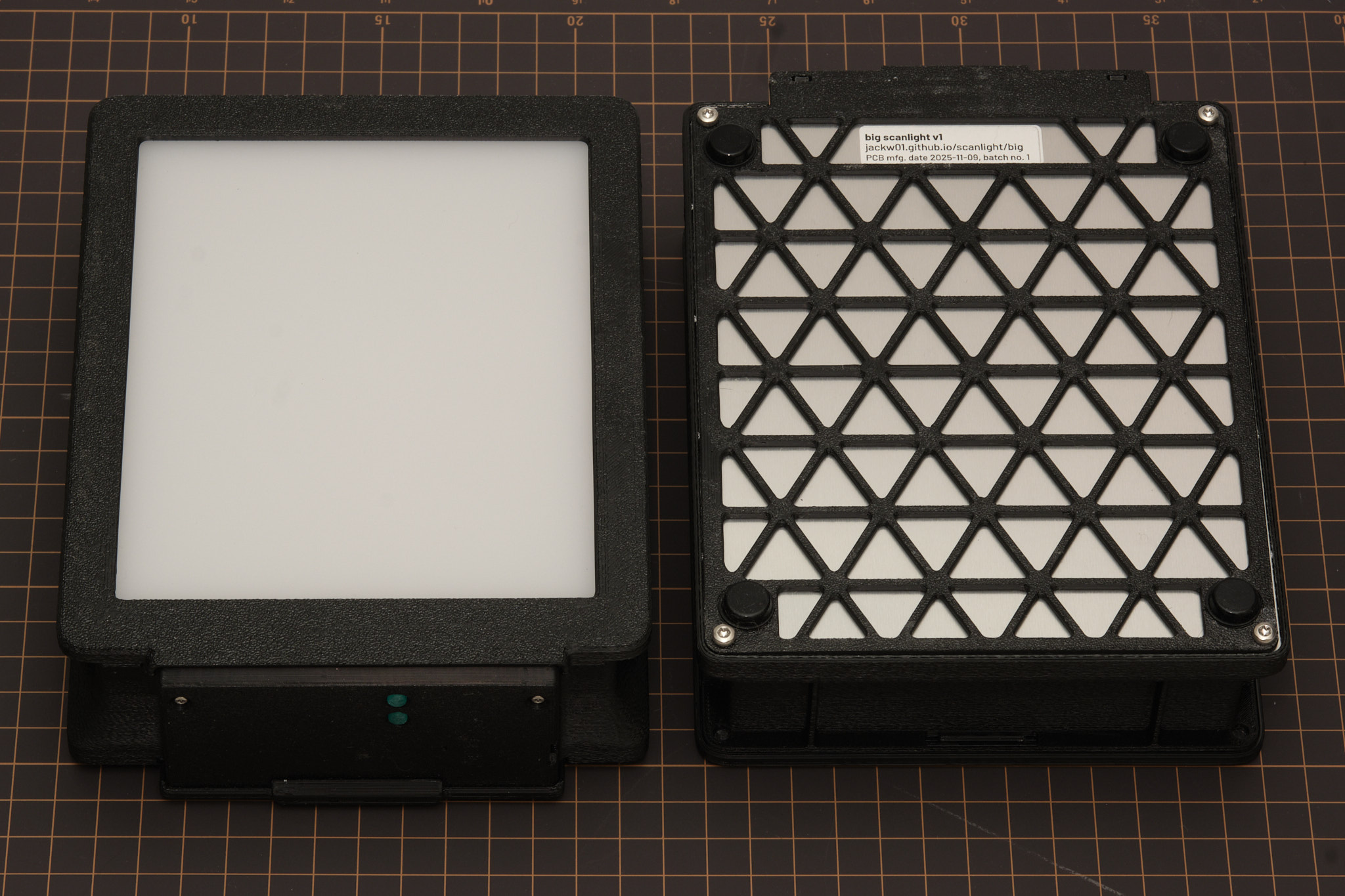
- Illuminated area dimensions: 108x134mm (approx. 4.25x5.25in)
- Suitable for use with 35mm, medium format, and 4x5 film
- 20 each of deep red (665nm), green (525nm), deep blue (455nm), and 5000K 95CRI white, and 16 infrared (850nm) LEDs mounted on aluminum PCB for optimal heat dissipation
- Up to 15EV brightness1 in RGB combined mode, 14EV in white mode
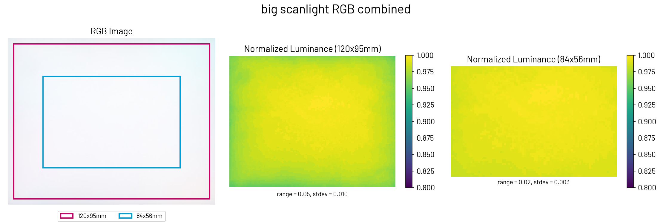
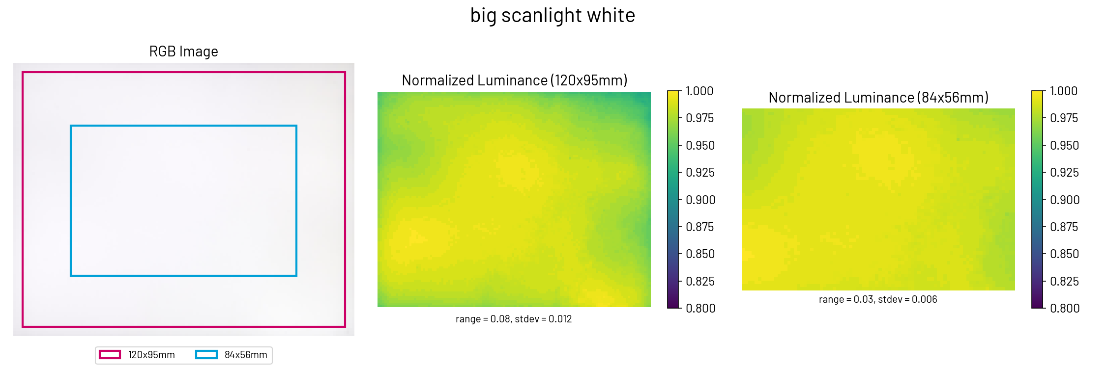
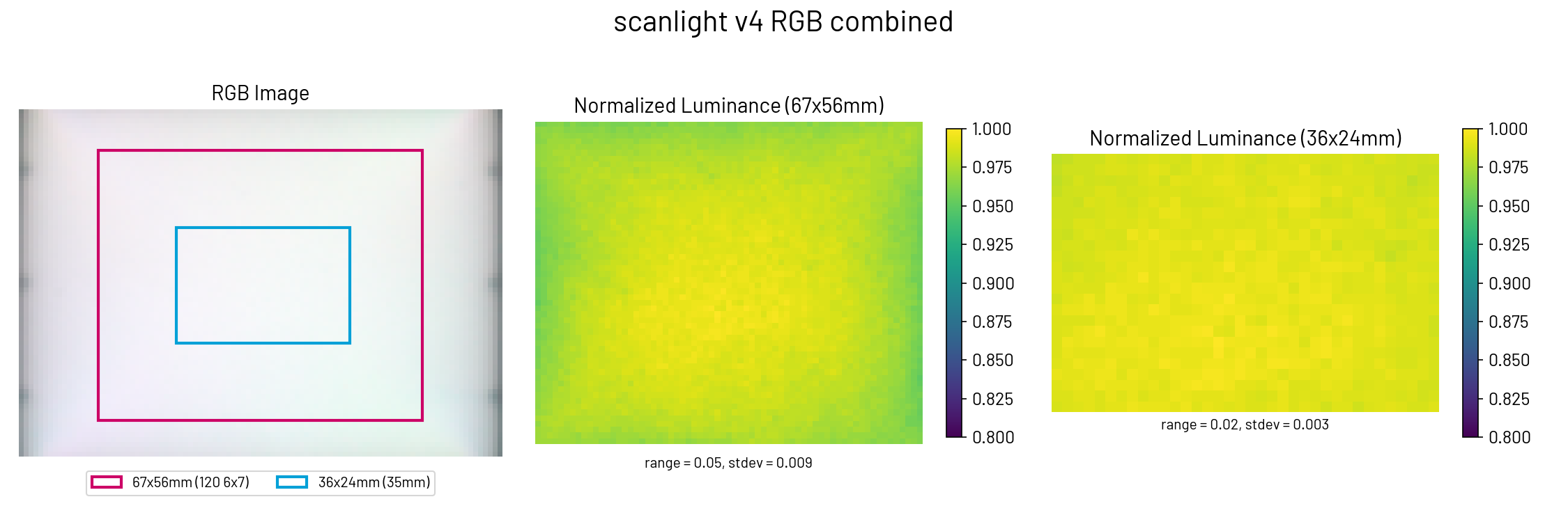
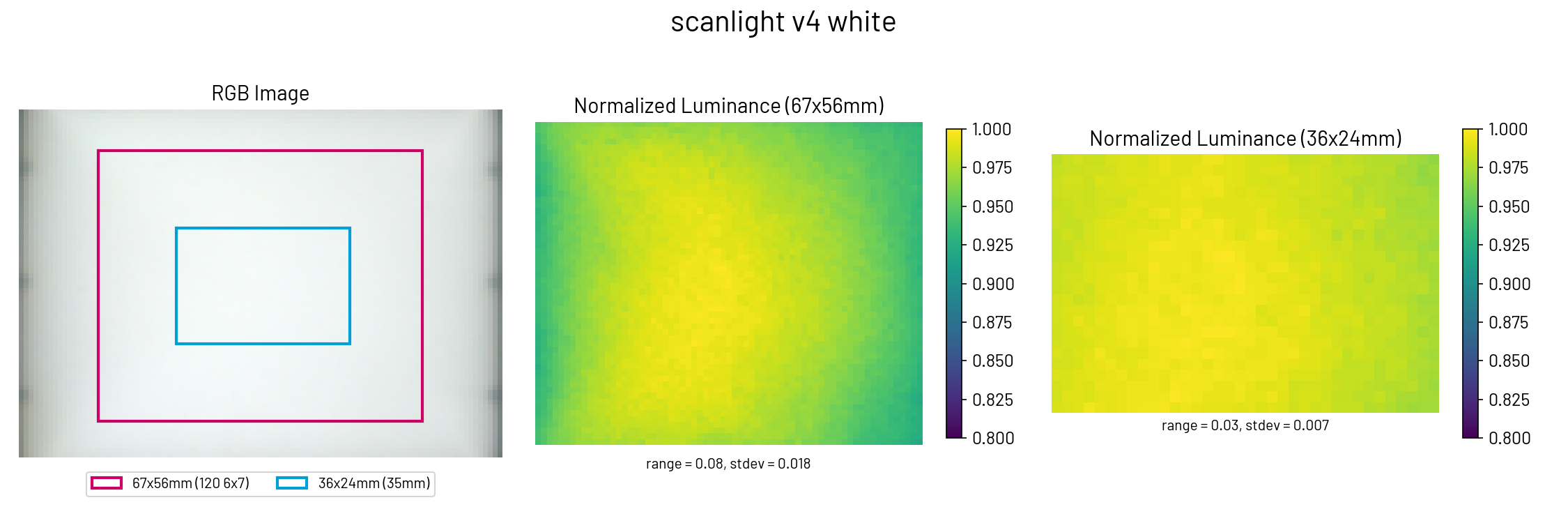
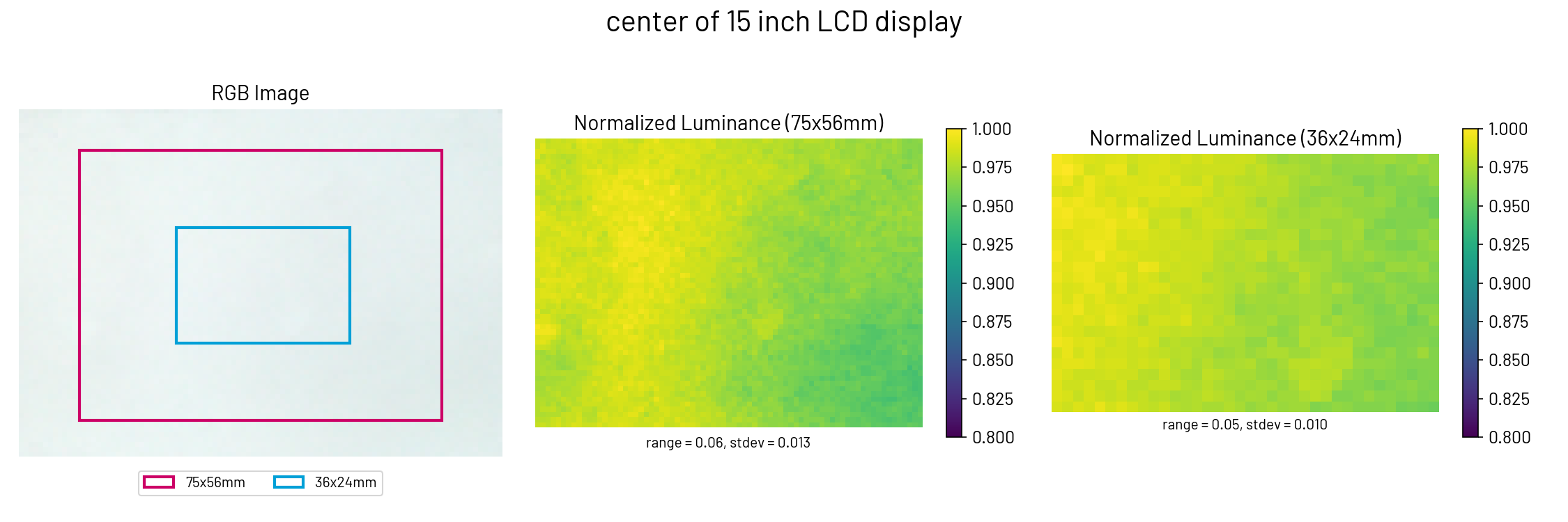
- Better light uniformity over medium format frame sizes than scanlight v2/v3/v4
- Diffuser made from fingerprint- and scratch-resistant textured acrylic
- 3D printed ABS housing
- Fully controllable via USB with web app
- On/off and mode toggle buttons on light source for standalone usage
- Compatible with accessories made for Negative Supply 4x5” light sources2
- Adapters available for compatibility with ToneCarrier and Valoi 360 Advancer
- Minimalist 35mm and medium format film carriers available
- Automated camera shutter control for capturing separate red/green/blue images
- Powered using any USB-C power source (at least 9V at 18W required for full brightness)
- Open source hardware and software
11/500s at f/8, ISO 100. Direct measurement of the light source (without film.)
2big scanlight’s diffuser panel is inside a 108x134mm, 1.5mm deep recess in the diffuser bezel, designed to accept masks and film carriers for Negative Supply 4x5” light sources. Check dimensions of accessories you plan to use before buying.
Original article on scanning film with narrowband light (with sample scans): A Better Light Source For Scanning Color Negative Film.
instructions

basic operation
The light source is powered via the left USB-C port. A USB-C PD power source that can supply at least 2A at 9V (e.g. most USB-C phone, tablet, and laptop chargers) is required to operate at full brightness; however, the light will still operate at reduced brightness from any USB power source capable of delivering at least 2A at 5V (e.g. almost all USB chargers from the last 10 years.)
It is not recommended to power the light from a USB port on a computer; a dedicated USB power supply should be used instead.
Press the upper button to toggle the light on and off. Press the lower button to toggle between narrowband RGB and 95CRI white modes. The buttons work even when the light is not connected to a computer. The default RGB channel brightnesses in this mode can be configured from the GUI, as explained below.
To adjust color and brightness and automate the process of scanning red, green, and blue channels separately, the light source can be connected to a computer via the right USB-C port and controlled with the web app located here. The web app requires a Chromium-based web browser.
In the Manual Control panel of the web app, the red, green, and blue channel brightnesses can be adjusted and the color channels can be turned on individually or together. In RGB (narrowband trichromatic) mode, the red, green, and blue LEDs are on at the same time. In White mode, only the 95CRI white LEDs are on. The red, green, blue, and infrared LEDs can also be turned on individually; the RGB channel brightness adjustments still apply in this case.
The RGB Presets panel of the web app allows RGB channel brightness settings to be stored to and loaded from web browser local storage, using the Load, Create, Rename, and Delete buttons.
The Set as Default and Load Default buttons refer to the default RGB preset, which is stored onboard the light source. This functionality is separate from presets stored in the web app and sets the RGB channel brightnesses used when the light is first powered on and when it is not connected to a computer.
remote shutter release usage
The 3.5mm jack can be connected to a camera so that the shutter can be remotely triggered from the web app to automatically capture images for each color channel. The length of the shutter trigger pulse and the delay after are both configurable. The default settings should work for most use cases. Operation in the R,G,B mode is shown in the timing diagram below; the other modes work similarly.

A cable with a male 3.5mm plug (otherwise known as a headphone connector) on one end and a camera-specific connector on the other end is required to use this functionality. A wide variety of these cables are available from online retailers; I cannot vouch for the quality of any of them or verify that a specific cable will work, as wiring diagrams are almost never published by the manufacturers. The design has been tested and works with several Fujifilm and Canon cameras that use the 2.5mm microphone jack as the remote shutter release input, with a 3.5mm to 2.5mm cable as well as a standard 3.5mm audio cable and 3.5mm to 2.5mm adapter.
On the original PCB revisions (26a902a/b marked on label), the 3.5mm jack is not electrically isolated. If planning to tether the camera to a computer while controlling the shutter using a light source with this PCB, test that the camera and cable are wired correctly first. Connect both the shutter control cable and a USB cable to the camera, and touch the tip of the 3.5mm plug to the exposed metal shell of the USB connector. If this does not trigger the camera shutter, the internal wiring of the camera or cable is likely reversed from the de facto standard and connecting the camera to both the light source and computer at the same time may cause issues. This PCB also does not connect the ring (focus) terminal on the 3.5mm jack, and requires a hardware modification to connect this terminal for remote shutter release compatibility with Nikon Z series mirrorless cameras. Units with this modification can be identified by light gray paint applied to the externally visible part of the 3.5mm jack.
frequently asked questions
See here
firmware updates
The web app will automatically notify if a firmware update is available and show a button to put the device into firmware update mode. To manually enter firmware update mode, press and hold down the DFU mode button while connecting the right USB-C port to a computer. The light source will show up as a USB storage device, and a firmware binary file can be copied to this device to update the firmware.
cleaning precautions
Cleaning the acrylic diffuser panel with cleaning solutions containing high concentrations of isopropanol, other organic solvents, or ammonia can cause crazing or cracking of the acrylic. If needed, use a cleaner meant for eyeglasses or a diluted household all-purpose cleaner like Simple Green. Do not spray liquids directly on the light source.
brightness trimming
In order to simplify the electrical design of the light source, the red, green, blue, and white color channels are split into two independently driven sides as shown below. The components used are very well matched, so the difference in brightness between the two sides should be a few percent at most and will generally not be noticed unless working with very low-contrast negatives. If there is a noticeable and consistent “split” in brightness or color across the centerline of the light source, the relative brightness of the two halves can be fine-tuned in the Brightness Trimming menu in the web app. Setting the trim values to a positive number increases the relative brightness of side 2; setting them to a negative number increases the relative brightness of side 1.

technical details
dimensions

film carrier compatibility
Adapters are available for improved usability with toneCarrier and Valoi 360 Advancer film carriers. Drawings of the adapters with critical dimensions are included below for reference; the dimensions of these third-party film carriers are not published by the manufacturers and are subject to change, so please use these drawings to verify compatibility with your film carriers before buying.
toneCarrier 35mm/120 adapter
 All dimensions in millimeters. This adapter is NOT compatible with the old 35mm toneCarrier design found on Printables.com.
Valoi 360 Advancer adapter
 All dimensions in millimeters. Mounting holes are sized for M4 socket head cap screws.
optical design
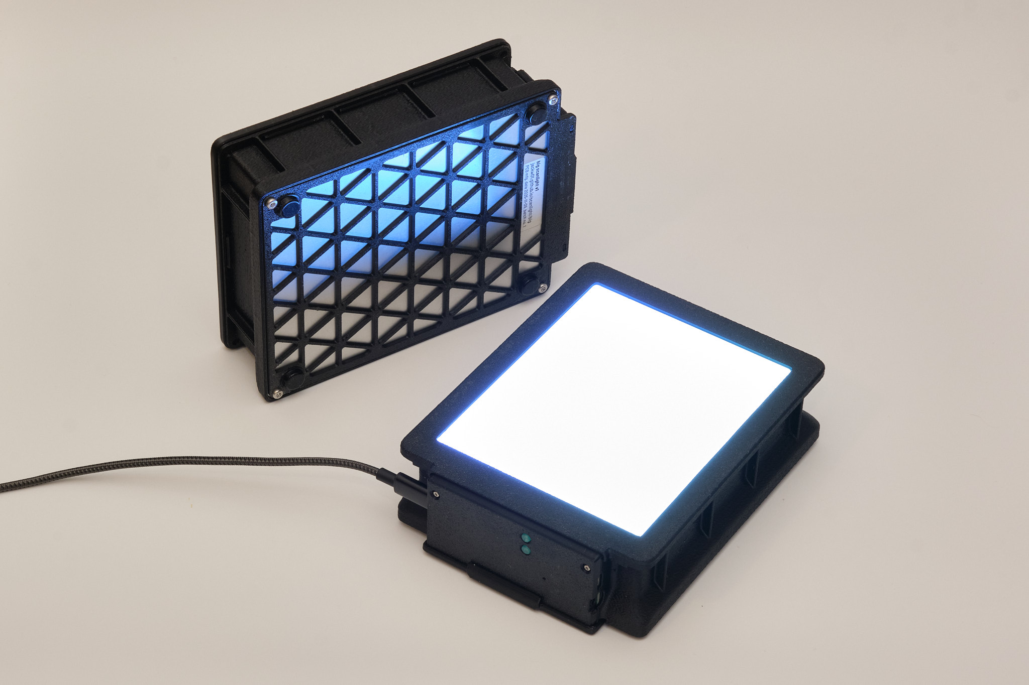
Big scanlight uses a very simple optical design consisting of a matte white acrylic diffuser panel, an LED array which spans the entire illuminated area of the diffuser, and a housing with diffusely reflective sidewalls perpenicular to the PCB and chamfered corners to reduce brightness falloff. In both RGB and white modes, big scanlight achieves similar lighting uniformity to scanlight v4 (slightly better than scanlight v2/v3) over a larger area.
PCBs
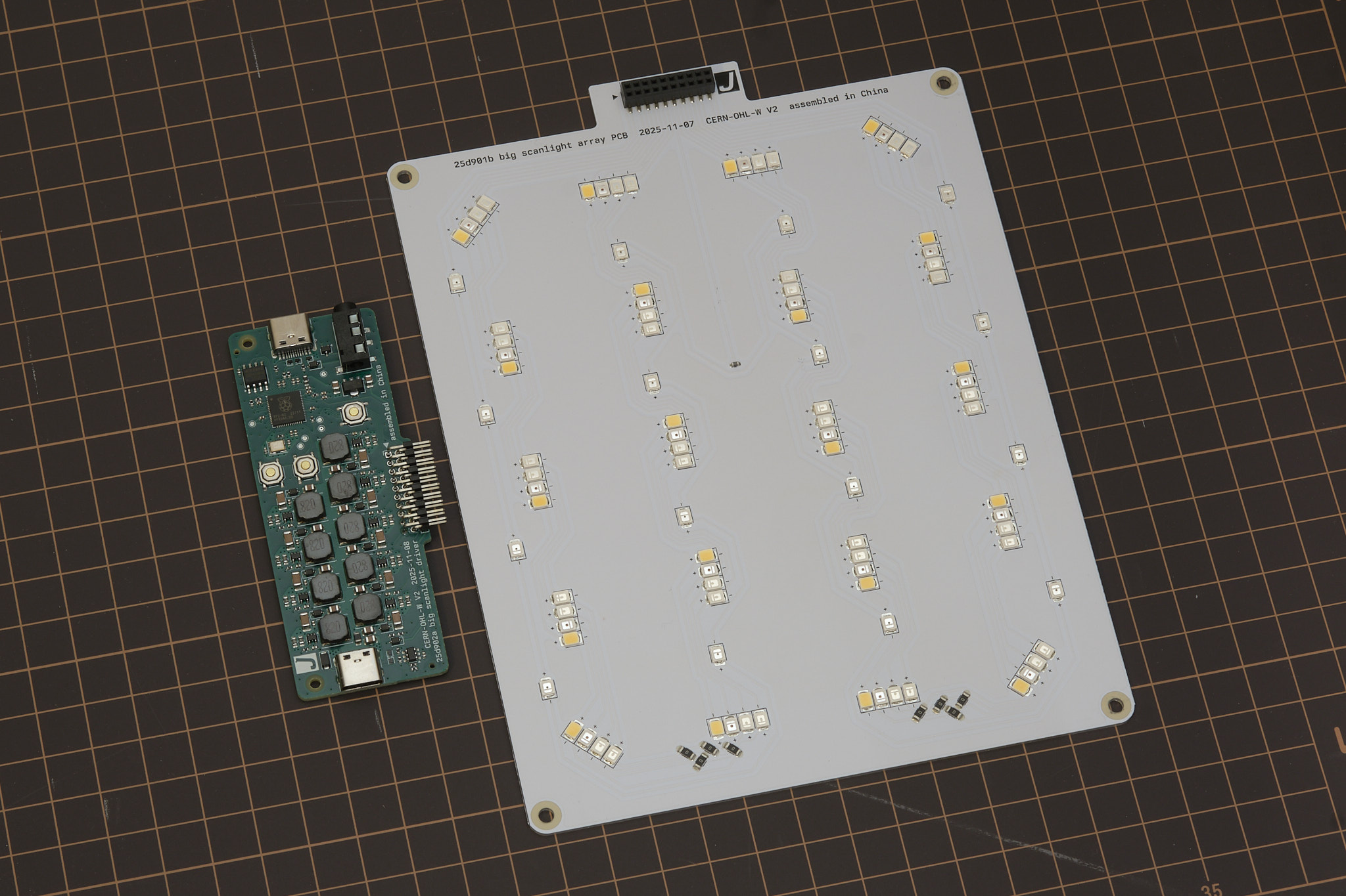
The driver PCB integrates a RP2040 32-bit ARM Cortex-M0+ microcontroller, nine TPS61169 constant-current boost converters configured for 80mA output current at up to 38V, and a CH221K USB-PD protocol controller on a 86x34mm four-layer PCB.
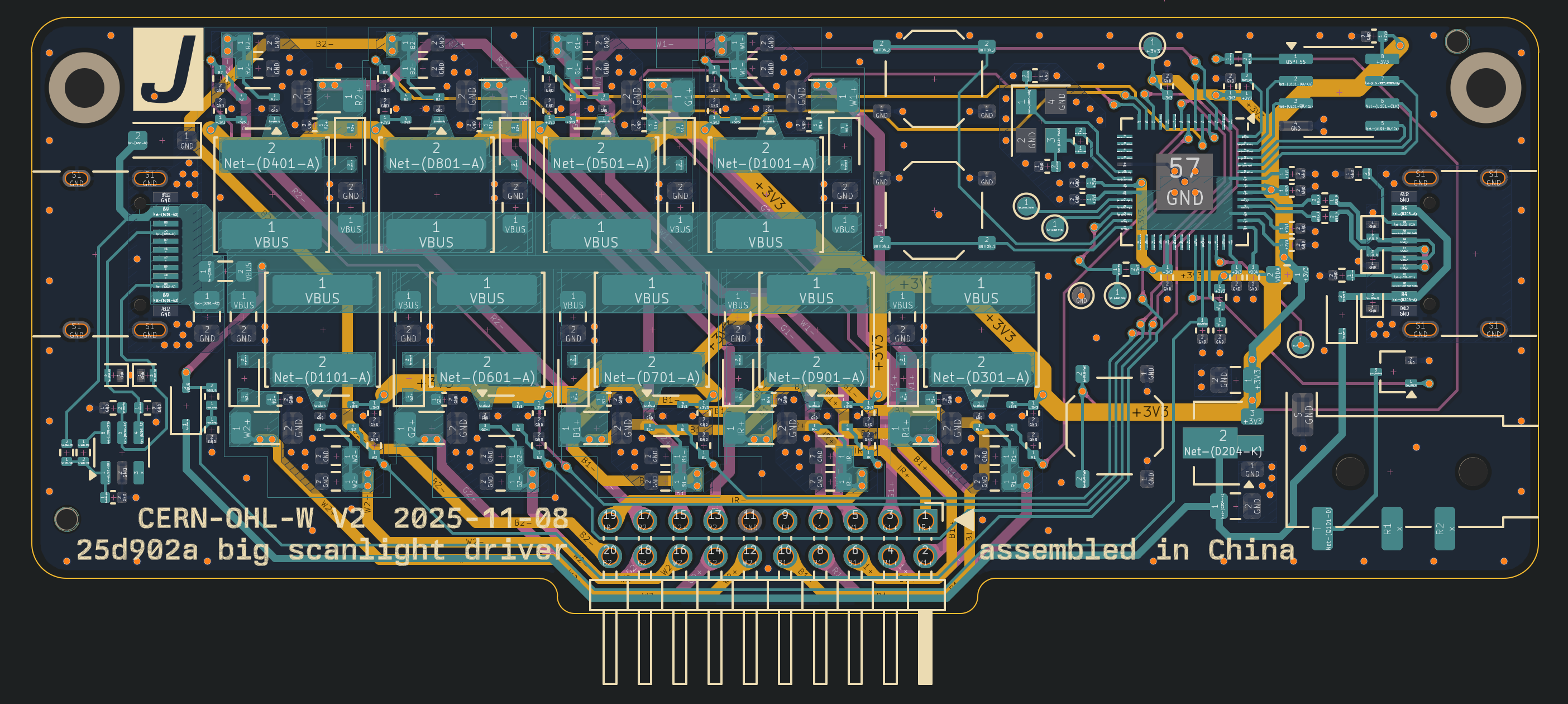
All design files for the driver pcb and LED PCB can be downloaded from the GitHub repository.
mechanical design
STEP files for all parts of the light source, film carrier adapters, and film carriers can be downloaded from the GitHub repository.
firmware and web app
The source code for the RP2040 firmware, a ready-to-flash firmware binary, and the source code for the remote control web app can be downloaded from the GitHub repository. The firmware is implemented using the RP2040 SDK and the web app is made with Vue and Vuetify.
Interested in building your own control software? The USB serial communication interface used by the firmware is fully documented here.
license
The PCB schematic, layout, and Gerber files and the 3D CAD files for this project are released under the CERN Open Hardware Licence Version 2 - Weakly Reciprocal (CERN-OHL-W V2). Software and firmware are released under the MIT License.